Selection Criteria for Cable Conductor Cross-Section
23 November, 2018
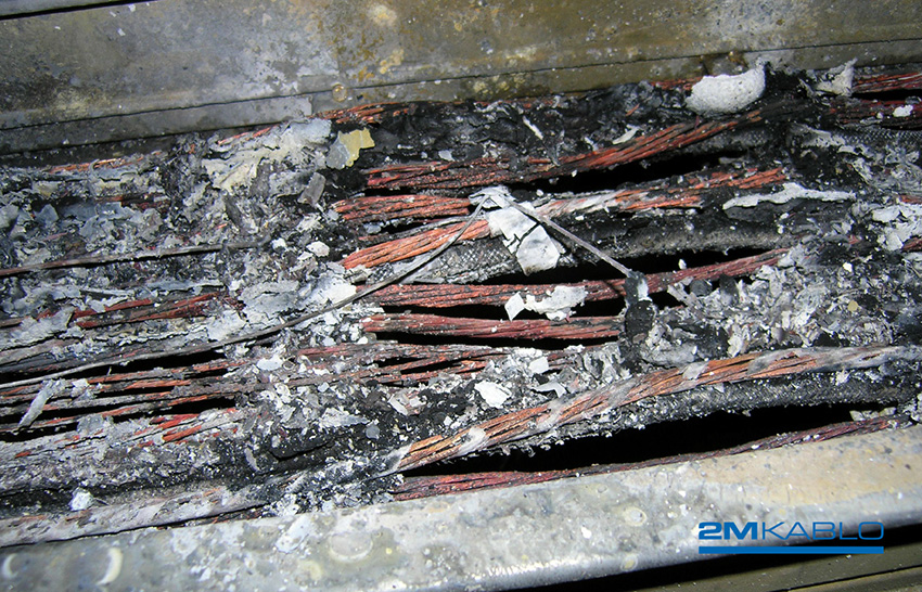
In facility costs, cables represent the largest share, making the choice of conductor cross-section critically important. An inappropriate selection can lead to overheating, resulting in cable damage and power outages.
- Undersized cross-sections cause excessive voltage drops, which may damage equipment.
- Oversized cross-sections unnecessarily increase installation costs.
- Therefore, selecting the optimal cross-section is essential for both safety and cost efficiency.
In long feeder systems, voltage drop is the primary challenge, while in short and heavily loaded installations, overheating becomes the most critical issue. If these criteria are not properly considered, frequent failures may occur, making it difficult to ensure the continuity of energy supply.
To prevent damage to the insulation material, the conductor cross-section of power cables must be selected according to the current they are required to carry. Any installation conditions that differ from standard practice must also be taken into account.
The line current drawn by the load is calculated using the following formula:
![]()
Where:
 = line-to-line voltage
 = power factors of the installation
Based on this current value, the appropriate conductor cross-section is selected from Table 1.
Under normal operating conditions, correction factors for current are not applied. These normal conditions are defined as:
- Ambient temperature of 20°C underground and 30°C in open air
- Maximum permissible conductor temperature of 70°C for PVC-insulated cables
- Installation depth of 70 cm for underground cables
- Use of fine, sifted sand as bedding material, placed 10 cm below and above the cable
- Specific thermal resistance of bedding material: 100 (°C·cm/W)
- Placement of protective bricks 10 cm above the cable in parallel installations, ensuring proper spacing and positioning
In cases where one or more of these conditions are not met, current correction factors must be taken into account. If the conditions differ from normal, the line current value is calculated using the formula:
![]()
Here, ![]() represent the correction factors applied when installation conditions deviate from standard values.
represent the correction factors applied when installation conditions deviate from standard values.
Cables, whether installed underground or overhead, have their current-carrying capacities defined according to the type of installation arrangement. These values are provided in standardized tables. Table 1 presents the current-carrying capacities of cables used in underground installations.
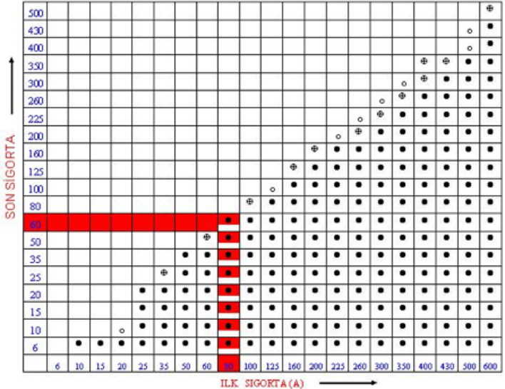
Table 1: Current-carrying capacities of power cables (0.6/1 kV) for underground installations under normal operating conditions. The maximum permissible conductor temperature is 70 °C.